
Calibration Process - Tuning
")


Video Stabilizer Tuning Guide
Video Stabilizer Tuning Guide
This page organises the stabilizer tuning process into a practical diagnostic workflow. Each check links to a detailed section below and points to the most likely calibration or tuning parameter to review.
It also contains a demo of the tuning tool to get quantitative metrics to evaluate the quality of the stabilisation performed by RVS, with insights and criteria on how to set the expectations regarding the quality of the results.
Finally, this page presents a series of use cases that are not covered by the RVS, as well as possible insights into how to tackle them.
Suggested order: verify geometric correctness first, then timing alignment, then tuning parameters, and finally validate with quantitative metrics.
-
Video Stabilizer Tuning Workflow
-
Check 1: Orientation consistency
Correction direction must match image motion. e.g. if the displacement is seen to the right on the frame, the correction should be to the left as well.- If incorrect, verify IMU-to-camera orientation. Please, check the IMU calibration process. Good correlation features are above 0.95
-
Check 2: Image rectification quality
Straight lines must remain straight and parallel, and the lens distortion should disappear at the output of the stabilisation.- If distorted, verify camera intrinsics and distortion. Please, check the Camera calibration process. Good RMS is usually below 1.0
-
Check 3: Motion amplitude consistency
Correction strength must match image motion. The objects placed at the centre of the scene (centre of the image) should remain centred.- If under or over-corrected, review camera calibration. Please, check the Camera calibration process. Good RMS is usually below 1.0
-
Check 4: Temporal alignment
Correction must not be ahead or behind the image. If the correction is performed ahead to the movement on the video, there is a temporal offset.- If leading or lagging, calibrate IMU timestamp offset. Please, check the IMU calibration process. Good correlation features are above 0.95
-
Check 5: Recovery after fast motion
Recovery time after wide or rapid movement- If too slow, reduce smoothing. Please, follow the section below to determine the Smoothing Coefficient.
-
Check 6: Cropping and FOV
Balance stabilization margin and visible field of view- Tune FOV scaling or crop margin. Please, follow the section below to determine the FOV scale.
-
Check 7: High-frequency vibration correction
Vibrational noise correction implies: 1) good camera-IMU synchronisation and 2) a good IMU sensor.- Review IMU lag and IMU noise performance. For the IMU lag, please check the IMU calibration process. Good correlation features are above 0.95
-
Check 8: Quantitative validation
SSIM should improve, and Jitter should decrease with the stabilizer. -
Known limitations and unsuitable cases
Zoom, rolling shutter, camera interface, sensor quality
-
Check 1: Orientation consistency
1. Orientation Consistency
Verify that the stabilizer-generated correction movement matches the direction of the image motion. This is one of the first checks to perform because an incorrect orientation makes all later tuning unreliable. This also requires simultaneous or a close-offset calibration to verify the correct correction.
Example of a good orientation:
Example (good case)
What to check
Observe whether the correction movement follows the same physical orientation as the apparent motion in the image. A tip is to place an object in the centre of the scene and move the camera in different directions. If the object is kept to the centre of the image, the orientation is adequate.
Check the IMU calibration. The correlation shall be at least 0.9
Symptoms
- Correction occurs in the wrong direction, displacing the object to a certain direction instead of keeping it to the centre.
- Image motion appears amplified instead of compensated
Likely cause
Incorrect IMU-to-camera orientation calibration.
Action
Check the orientation mapping between IMU axes and camera axes.
In GStreamer, the orientation is given by the imu-orientation property.
If the movements happen in the opposite direction, invert the axis (x -> X) or (X -> x).
Please, check the IMU calibration process
2. Image Rectification Quality
Confirm that the input image is properly rectified before evaluating stabilisation. Rectification errors are often visible as curved or non-parallel lines and can corrupt the estimated motion model.
Example of a distorted (left) and a rectified image (right, still improvable):
Example (distorted)

Example (undistorted)

What to check
Straight scene lines should remain straight, and parallel lines should stay parallel across the image.
Check the camera calibration results. The RMS should be below 1.0.
Select the proper lens model when calibrating and stabilising.
Symptoms
- Warped lines
- Distorted geometry during motion
Likely cause
Incorrect camera intrinsic or distortion parameters.
Action
Re-check camera calibration and confirm that the correct distortion model is being applied.
Check that the RMS values are below 1.0 (brown-conrady).
In case of needed brown-conrady in CUDA (not available yet), skip the distortion parameters.
Please check Camera calibration process
3. Motion Amplitude Consistency
Verify that the strength of the correction matches the strength of the motion in the image. A stabilizer can fail even When the direction is correct, the scale of the estimated motion is wrong.
What to check
Compare image motion amplitude with correction amplitude during representative sequences.
Symptoms
- Residual shake due to under-correction
- Oscillation or exaggerated response due to over-correction
Likely cause
Incorrect camera calibration, especially focal length or distortion terms.
Action
Validate intrinsics and distortion again and confirm that the active configuration matches the device being tested.
Check that the RMS values are below 1.0 (brown-conrady).
In case of needed brown-conrady in CUDA (not available yet), skip the distortion parameters.
Please check Camera calibration process
4. Temporal Alignment and IMU Lag
The correction movement must not occur before or after the image motion. Temporal mismatch is one of the most common causes of unstable or unnatural stabilisation.
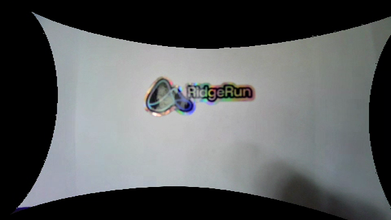
Example of disalignment
Observe the logo: it moves widely to the sides

Example of alignment
Observe the logo: it is almost kept to the centre

What to check
Observe the timing relationship between image motion and correction motion during fast directional changes.
Place an object at the centre of the scene. When moving the camera, the object must remain centred.
Symptoms
- Correction appears ahead of the image
- Correction lags behind the image
Likely cause
Incorrect IMU-camera timestamp offset or synchronisation error.
The camera is not providing an accurate timestamp (start-of-frame).
Action
Recalibrate the IMU lag or timestamp offset using motion sequences with strong, clear transitions.
The IMU calibration correlation must be at least 0.95 in all axes.
Please, check the IMU calibration process
5. Recovery After Fast Motion
After a wide and rapid movement, the stabilizer should return to a steady state quickly enough for the intended use case. Excessive recovery time typically points to overly aggressive smoothing.
Large smoothing coefficient
Observe that a large smoothing coefficient leads to a slower recovery.
Small smoothing coefficient
Observe that a small smoothing coefficient leads to a fast recovery.
What to check
Observe how long it takes for the frame to settle after a fast pan, jerk, or abrupt repositioning.
Symptoms
- Slow return to steady framing
- Long transient response after rapid movement
Likely cause
Smoothing coefficient is too strong for the required responsiveness.
Action
Reduce the smoothing coefficient until recovery time is acceptable.
6. Cropping and Field of View
Stabilization always trades usable field of view against correction authority. The selected cropping area must match the practical needs of the application.
Small FOV
Smaller FOV (< 1.0) crops the image
Large FOV
Smaller FOV (> 1.0) expands the image
What to check
Assess whether the visible crop is acceptable while still providing enough correction margin.
Symptoms
- Excessive crop
- Insufficient stabilization margin
Likely cause
Field-of-view scaling is not matched to the application target.
Action
Tune FOV scaling or crop margin to balance image coverage and stabilisation strength.
7. High-Frequency Vibration Correction
Vibrational motion requires both good temporal alignment and sufficiently low IMU noise. If not properly handled, micro-jitter remains visible in the stabilized result.
Example
For slow movements, the object is stabilized but vibrational is amplified.
What to check
Use vibration-heavy movements and inspect whether high-frequency disturbances are suppressed.
Symptoms
- Visible micro-jitter
- Buzzing appearance in the frame
Likely cause
IMU lag error, poor synchronisation, or excessive IMU noise.
Action
Review IMU lag calibration and evaluate whether the selected IMU is adequate for the vibration profile.
Add digital video stabilisation (DIS) after the RVS.
8. Quantitative Validation
In addition to visual inspection, validate the output using objective metrics. The stabilized output should outperform the original sequence.
Expected result
SSIMof the stabilized sequence should be better than the originalJittershould be lower than the original
If metrics do not improve
- Re-check synchronization
- Re-check camera calibration
- Review smoothing and crop settings
Using the command line
If a CLI tool is preferred, it is possible to use the rvsanalyze element.
An example pipeline:
GST_DEBUG=rvsanalyze:LOG
gst-launch-1.0 nvarguscamerasrc ! nvvidconv ! rvstabilize ... ! nvvidconv ! video/x-raw,width=480,height=270 ! rvsanalyze ! fakesink
9. Known Limitations and Not Suitable Use Cases
Large zoom scales
The larger the zoom factor, the more sensitive the system becomes to IMU noise and calibration error.
Uncorrected vibrational noise
If vibration cannot be corrected sufficiently, add a digital video stabilizer. This capability is currently under development.
IMU selection
The BMI160 is known to be noisier than the ICM42688. Prefer the ICM42688 or a better alternative when possible.
Extreme rolling shutter
A strong rolling shutter can introduce wavy or wobbly artefacts that reduce stabilisation quality. An extension is needed to mitigate rolling-shutter
Network cameras
These cameras typically do not provide a Start of Frame timestamp and are therefore not recommended for RVS.
USB cameras
These often require additional synchronisation and calibration effort compared with more tightly integrated systems. It is possible to synchronise with IMU calibration process
Stitched images
Having multiple cameras or stitched video is not currently covered. A suitable solution is still under research.