Qualcomm Robotics RB5/RB6 - Hardware Capture Subsystem
This section gives you an overview of the Capture Subsystem of the Qualcomm Robotics RB5/RB6[1].

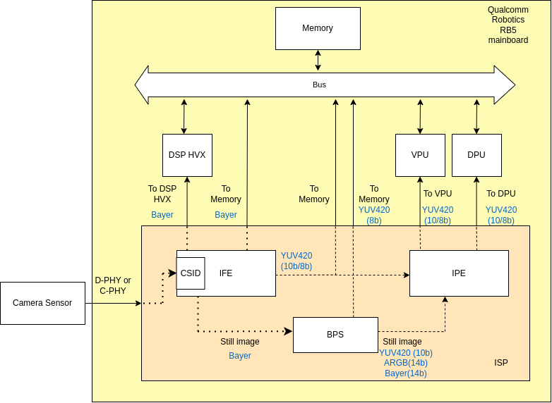
Figure 1 consists of a diagram with the main Hardware components and data paths of the Capture Subsystem. The text in color blue shows the format of the data in the specific path. Note that the lines connecting the components on the diagram and the direction of the data flow in those connections are predetermined and fixed.
Camera Sensor
The camera sensor communicates with the mainboard through its 6 4-lane MIPI CSI-2 protocol interfaces using either C-PHY 1.2 or D-PHY 1.2 layers. The data from the camera first reaches the CSID (CSI Decoders) inside the Image Front-End (IFE) of the Qualcomm Spectra 480 ISP.
Image Front-End (IFE)
The Spectra 480 ISP contains 2 Full IFE's for processing 25MP (4:3 or 18MP (16:9) input resolution sensors and 5 IFE_lite to process 2MP input resolution sensors for miscellaneous CV use cases.
The Image Front-End's data outputs are:
- Raw bayer frames for the Hexagon DSP Hexagon Vector Extensions streaming.
- Raw Bayer frames to memory
- Two data lines of YUV420 10bits or 8bits frames going directly to memory and to the Image Processing Engine (IPE) for post-processing
- Raw Bayer snapshots to the Bayer Processing Segment (BPS)
Bayer Processing Segment (BPS)
The Bayer Processing Segment's data outputs are:
- YUV420 8 bits image to memory
- YUV420 10 bits, ARGB 14 bits or raw Bayer 14 bits to the Image Processing Engine (IPE)
Image Processing Engine (IPE)
The Image Processing Engine's data outputs are:
- YUV420 10bits or 8bits to the Video Processing Unit (VPU) for encoding.
- YUV420 10bits or 8bits to the Display Processing Unit (DPU) for display.
References


