
Birds Eye View - Real Time Birds Eye View Calibration Guide
| ⇦ User Guide/Minimal Application | Home | GStreamer/GstBEV Plugin ⇨ |
 |
| Getting Started |
|---|
| User Guide |
| Calibration Guide |
| GStreamer |
| Performance Measurements |
| Contact Us |
 | Birds Eye View RidgeRun documentation is currently under development. |
The calibration tool allows you to generate a Birds Eye View (BEV) configuration file directly from your browser. This configuration (or calibration) can be then used with the Birds Eye View project.
Understanding the Calibration Process
The calibration process consists on generating a JSON file with the appropriate parameters to build a Birds Eye View scene from your camera setup. The following figure summarizes the process.

- 1. Prepare calibration images
- The process starts by you preparing one image per camera, each containing a square pattern. The calibration images must be taken in the same physical configuration of the final setup. Refer to #Preparing the Calibration Images for more details.
- 2. Calibrate the scene
- Use our online Birds Eye View Calibration Tool to calibrate the camera configuration. This can be done on any computer. It is not necessary to do this in the target hardware. Refer to #Using the Calibration Tool for more details.
- 3. Export the calibration file
- The calibration tool exports a JSON file that you can dump into the target hardware.
- 4. Generate the Birds Eye View scene
- In the target hardware, use the calibration file along with the BEV software to generate the aerial view from the cameras in real time.
- 5. Validate the resulting scene
- If everything went okay, the result should be exactly the same as you calibrated in the calibration tool. It may be necessary to iterate the calibration process again to fix perspective artifacts.
Preparing the Calibration Images
Before any calibration takes place, you must prepare a set of calibration images. Consider the guidelines below in order to prepare these samples:
- You must have a physical setup with your cameras in place. Take, for example, our testing structure:

Example of a test structure. - The resulting calibration will only work for this setup. If you move the orientation of a camera, you must recalibrate.
- Make sure that the cameras have some overlap between them.
- The cameras should cover the complete 360 view of the scene
- Take a picture from each camera.
- The orientation and rotation of the cameras do not matter, as it may be fixed during the calibration process
- The picture must from a Rectilinear lens, Fisheye lenses must be rectified first. Check out our CUDA Undistort project if you are looking for solutions to convert from Fisheye to Rectilinear.
- To get the best results, consider performing the lens distortion calibration for each camera individually
- The picture must have a square pattern in it. Here are some guidelines regarding the pattern:
- It must be square, or contain a square in it.
- The bigger, the better.
- Chessboards, ArUco Markers, April Tags, are good square pattern examples.
- All the patters should be in the same surface, typically the floor.
- Must be placed in a flat surface and can't be curved, crumpled or have folding marks.
- The closer the pattern to the camera center, the better

A, B and C: Good calibration patterns. D: Square not easily detectable. E: Crumpled pattern, not in the floor. F: Pattern is not flat and not in the floor.


Sample Calibration Images
The following set is a series of sample image you may use to play with the calibration tool. The square tiles may be used as the square pattern.
-
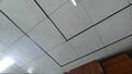
Camera 0
-
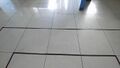
Camera 1
-
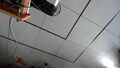
Camera 2
-
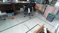
Camera 3
-
Camera 4
-
Camera 5


The resulting Birds Eye View is shown below. Each camera is is overlayed as a hint to aid you in the calibration process.

The Calibration Tool GUI
Once you have the calibration images available, use RidgeRun’s Calibration Tool to start the calibration process. This section guides you on the process on how to perform it.
Once you launch the tool, the Home Screen will appear, displaying the available calibration’s tools. For this wiki, we will focus on the BEV calibration tool. Simply click on it to proceed.

After selecting the BEV Calibration Tool, you will be greeted by its Home Screen, which includes:
- A brief description of the BEV Calibration Tool.
- A Start Calibrating button to get into the actual calibration tool.
- A card linking to the full documentation for BEV and Libpanorama.

To continue, click Start Calibrating. This opens the Main Window of the BEV Calibration Tool, which is composed of four main sections:

- Header: Tools header. Click on the RidgeRun's logo to return to the Home Screen.
- Control Panel: Contains the primary controls for managing the calibration process, from loading the calibration images to exporting the calibration results.
- Cameras Panel: Shows thumbnails of the loaded images and provides some image-specific controls that change based on the current calibration step.
- Working Area: In this area, you will interact with the images and active calibration tools. Allows seamless switching between images without losing your progress.
Control Panel
- Hide/Show: You can hide/show this panel by clicking this button.
- Save Project: Save the project to continue later.
- Open Project: Load existing project.
- Add Source: Add the pictures you will use for calibration.
- Export Calibration: Export your calibration.
- View Cameras: The tool has 2 different views. The first one is the Cameras View, click here to change to this view. Use it to change the perspective of the individual pictures.
- View Bev: The second view is the BEV (Birds Eye View), click here to change to this view. Once you get the perspective of all the pictures, you can go to the BEV View to start generating your BEV.
- Settings: Open the Settings Panel (see Settings Panel section for more details)
- Take a Tour: Take an interactive tour through the GUI interface.
- Help: Link to the RidgeRun’s BEV calibrator documentation.
- Contact Us: Contact RidgeRun for additional support.
Cameras Panel
The Cameras Panel allows you to add the calibration images. Once added here you will find a preview thumbnail of all your pictures.
- Add Images: Click this button to open a file selection dialog and select your calibration images. You can import several images at once by holding shift or ctrl and selecting multiple files.
- Thumbnail: Each thumbnail contains a preview of the picture, its name, and more. You can click any of the thumbnails to set it as the active picture and start editing.
- Thumbnail Toolbar: Contains controls for the image. The toolbar changes based on the current view. (See Thumbnail Toolbar section below for more details).
- Thumbnail Title: Indicates the name of the picture it represents. By clicking this button the Thumbnail Menu appears (See Thumbnail Menu section below for more details).
Thumbnail Toolbar
The thumbnail toolbar contains controls specific to an image. It changes depending on the current view , check out below the toolbar appearance for Cameras View and Bev View.
- Delete Picture: Delete the current image (available in both views).
- Picture Reload: Undo any modification to the picture and start from scratch.
- Picture Lock: Lock the picture and avoid any accidental editing. When enabled you can’t move, scale, rotate, or change the roi.
- Picture Filter: Use this button to show only this picture.
- Picture Visibility: Show/Hide current picture.
Thumbnail Menu
The thumbnail dropdown menu appears when you click on the thumbnail title, it contains controls to modify the image results. The controls change with the view, below are shown the appearance for Cameras View and BEV View.
- Scale: Scale the transformed image results for this factor. Reflected until you click the Apply button in the Main Toolbar. (Cameras View)
- X Offset: Normalized offset in the horizontal axis of the transformed image, can be positive or negative. This moves the result image left or right, changing the visible area of the transformed image, anything outside the visible area may not be available for BEV depending on the output resolution. Reflected until you click the Apply button in the Main Toolbar. (Cameras View)
- Y Offset: Normalized offset in the vertical axis of the transformed image, can be positive or negative. This moves the resulting image up or down, changing the visible area of the transformed image; anything outside the visible area may not be available for BEV depending on the output resolution. Reflected until you click the Apply button in the Main Toolbar. (Cameras View)
- Width: Adjust the width of the image in the Main View. Also reflects the current width when you modify it with the mouse. (BEV View)
- Height: Adjust the height of the image in the Main View. Also reflects the current height when you modify it with the mouse. (BEV View)
- Angle: Change the image rotation in degrees. The rotation is performed from the center of the image. Also reflects the current angle when you modify it with the mouse. (BEV View)
Working Area
- Title Bar: Indicates the current view and the active picture name.
- Main View: Main view is where you will edit your pictures and compose the BEV.
- Results View: Whenever you apply the modifications to a picture, the result will be shown here.
- Main Toolbar: Contains controls to edit your pictures, changes depending on the current view.
- Zoom Bar: More controls to change the size and position of the pictures.
- Position Bar: Shows the pointer position relative to the picture and relative to the view window.
Main Toolbar
- Delete Tool: Deletes the square vertices points of the active image for Cameras View and removes the ROI in the active image for BEV View.
- Polygon Tool:
- Cameras View: Use the Polygon Tool to mark the position of the square pattern for each picture.
- Bev View: Use the tool to draw a Region of interest (ROI) in each picture. Any areas outside of the ROI will be ignored. Shortcut Tip: You can hide/show the areas outside the ROI by pressing Shift + Click.
- Scale Tool: Allows to scale and rotate the pictures.
- Apply: Executes the image perspective transformation in the Cameras View and generates the BEV composition in the BEV View, the results will be shown in the Results View.
Zoom Bar
- Zoom Controls: Zoom in and zoom out in any view. You can also write the zoom percentage manually.
- Fit to Screen: Automatically adjust the view content to the view window visible area.
- Fullscreen: Toggle to and out of fullscreen, when enabled the current view window will occupy the space of the full working area.
Position Bar
- Pointer position relative to the picture top/left corner.
- Pointer position relative to the view window.
Settings Panel
- Opacity: Sets the opacity of the images in the BEV Main View, 100 for full opacity and 0 for full transparency.
- Overlay: Define overlay image for the BEV Composition
- Grid: Define a grid of vertical and horizontal lines overlaid over the Main and Results View.
- Output Resolution: Define the output size of the BEV image. This changes the frame displayed in the BEV Main View.
- Close Settings: Closes the Settings Panel.
- Overlay Check: Show/Hide overlay image in the BEV Main View.
- Overlay File: Shows current overlay image or “Overlay File” as a placeholder
- Add Overlay: Selects the overlay image file, when hit it opens a file dialog window.
- Grid Width: Number of divisions along the horizontal axis.
- Grid Height: Number of divisions along the vertical axis.
- Output Width: Bev output image width.
- Output Height: Bev output image height.
Performing the Calibration
The calibration is a highly iterative and time consuming process. In general, you can expect to follow this process:

Inverse Perspective Transform
The purpose of this stage is to convert each individual image into the aerial view. You do so by outlining the square calibration pattern in each image.
- Start by clicking the thumbnail of the image to which you desire to perform the IPT. The image will be displayed in the working space.
- Select a corner of the pattern by clicking (and dragging) on it.
- Use the precision visualizer to click at a pixel-level precision.
- You may drag the point you just placed to adjust its location.
- Click and hold to start the placement of the second point.
- Use the vertex and the pattern contour to aid you in the placement.
- Again, use the precision visualizer.
- You can, again, drag the new point to adjust its location.
- Repeat the last step for the 3rd and 4th corners.
- The square will close automatically.
- The warped image will be reflected immediately below.
- The warped image will be reflected in the BEV thumbnail and workspace.
- Adjust any point as needed.
- Click on a new location to start the process again
- Adjust the zoom level as needed
- Information discarded by the zoom will not be available in the BEV workspace.
- Keeping too much information (zoom out) will make the image uncomfortable to manipulate in the BEV workspace.
- Zoom can be adjusted at any time.
Note that if the original images have lens distortion, you might see curvature in straight lines even after performing the IPT |

Build Birds Eye View
The purpose of this stage is to combine all of the IPT images into a single BEV image. Note that no blending will be made. Use the Visibility and Reordering tools to help you find the best overlap.
- Make sure you have performed the IPT for all the images.
- Click on the Birds Eye View thumbnail.
- Choose your desired output image size and set it on the control bar
- Use the Reorder controls to place the image you wish to work on at the top of the image bar
- Resize the image, rotate it and place it at the desired position.
- You can use the Lock control to avoid further accidentally moving the image.
- You can always come back and manipulate this image again.
- Place the next image at the top of the image bar to bring it to the front of the BEV.
- Adjust the position, rotation and size to find the best overlap between the two images.
- Use the Visibility controls to quickly evaluate the quality of the overlap.
- Use the Reorder controls to swap positions and evaluate the quality of the overlap.
- If you are happy with the results you can lock the image in place.
- Repeat the process for all the images.
- Don't hesitate revisiting previous images to adjust their configuration.
- You can always go back to the individual image and adjust the zoom level.
Sometimes selection can be tricky. If you experience problems, click on the empty canvas and retry selecting the image
Don't expect a perfect match! The different perspectives of the cameras will always cause disparity defects. |

Region of Interest Selection
The purpose of this stage is to select the portion of each individual image you wish to keep and use for the image blending. Generally, big overlaps produce unnatural effects, while small overlaps in strategic zones produce smoother transitions.
- Make sure you have built the BEV image already.
- Click on the ROI selection button in the toolbar.
- Use the Reorder controls to place the image you wish to work on at the top of the image bar
- Click (and drag) the first corner of the region of interest.
- Use the precision visualizer to help you hit the right location.
- Once dropped, you can move the point to adjust its location.
- Repeat the process for as many points as needed.
- Close the polygon by dragging the last point on top of the first one. The outside of the polygon will color up to indicate that the polygon is closed.
- Use the Reorder controls again to bring the next image to the top.
- Create the ROI polygon for this new image.
- Use the Reorder controls to swap positions and evaluate the quality of the ROIs overlap.
- Focus on the overlap region between the images. Remember that there may be overlap between multiple images!
- Repeat the process for all the images.
- Don't hesitate revisiting previous images to adjust their configuration.
ROIs can be tricky, experiment with different areas and positions. |

Export the Calibration File
Once you have the BEV and ROIs selected you are finally ready to export the calibration file.
- Make sure you have built the BEV image already and the ROIs are properly selected.
- Click on the JSON export button in the toolbar.
- Use the Copy icons within the json to copy valid JSON content.
- Paste the contents in a file of your choice. The name is not important.
- The exported JSON defaults to the sample images. Make sure to modify it for your use case:
- The location in each camera pipeline.
pipeline: "filesrc location=samples/bev_6_cameras/cam_0.jpg ! jpegparse ! jpegdec ! queue ! videoconvert ! video/x-raw,format=RGBx ! imagefreeze ! appsink name=appsink drop=false sync=true qos=false max-buffers=1 max-lateness=-1"
- The location, size and position of the overlay image
- You may remove the overlay portion of the JSON if you do not wish to render an image on top of the BEV.
- You may modify the camera pipelines to use the actual cameras or videos
  overlay: {
    pipeline: "filesrc location=samples/bev_6_cameras/top_car.png ! pngparse ! pngdec ! videoconvert ! videoscale ! video/x-raw,format=RGBx,width=600,height=550 ! appsink name=appsink"
    x_pos: 240
    y_pos: 650
  }
Don't close the browser window just yet! You might need to iterate refine the BEV and there's no way to save your progress |
Don't copy using CTRL+C, copy using the icons within the JSON. |

Test in the Target Hardware
You are finally ready to test the calibration result in the target hardware.
- Make sure you have exported a valid calibration file.
- The easiest way to test is by using the birds_eye_view example provided in the project.
- At the root of the project, execute the following command:
- This assumes the build directory was set to builddir.
- This assumes the calibration file was saved to /tmp/calibration.json.
- If you followed the build instructions, it should work out of the box
builddir/examples/birds_eye_view -p /tmp/calibration.json
This calibration file works not only with the example, but with your custom applications as well! |
