RidgeRun Video Stabilization Library/Useful Links/BMI160 Setup: Difference between revisions
No edit summary |
|||
| (One intermediate revision by one other user not shown) | |||
| Line 7: | Line 7: | ||
The BMI160 sensor has 12 pins, as shown in the picture below. To use it, connect the VIN pin to a 3.3V signal, the GND pin to ground (0V), the SCL pin to the I2C clock, and the SDA pin to an I2C data pin. For example, refer to the NVIDIA Jetson Nano Developer Kit's Expansion Header Connections in the second image below. The connections should be made in this case, as illustrated in the last image. | The BMI160 sensor has 12 pins, as shown in the picture below. To use it, connect the VIN pin to a 3.3V signal, the GND pin to ground (0V), the SCL pin to the I2C clock, and the SDA pin to an I2C data pin. For example, refer to the NVIDIA Jetson Nano Developer Kit's Expansion Header Connections in the second image below. The connections should be made in this case, as illustrated in the last image. | ||
To access the I2C bus the user needs to have the right permissions. Run the following command to include the user in the I2C group. | To access the I2C bus the user needs to have the right permissions. Run the following command to include the current user in the I2C group. | ||
<syntaxhighlight lang=bash> | |||
sudo usermod -aG i2c $USER | |||
</syntaxhighlight> | |||
Reboot board to apply change. | |||
<br> | <br> | ||
| Line 14: | Line 19: | ||
| type = content | | type = content | ||
|small=left | |small=left | ||
| text = '''NOTE''': Its I2C address can be found on bus number 7 (Jetson Nano) or 8 (Jetson Xavier NX) and the 0x69 address. The bus number can be found in the 40-pin header description for the platform (NVIDIA case). | | text = '''NOTE''': Its I2C address can be found on bus number 7 (Jetson Nano and Jetson AGX Orin) or 8 (Jetson Xavier NX) and the 0x69 address. The bus number can be found in the 40-pin header description for the platform (NVIDIA case). | ||
|style=width:unset; | |style=width:unset; | ||
}} | }} | ||
Latest revision as of 14:07, 3 March 2025
Table of Contents
[Sticky]

|
BMI160 sensor setup
The BMI160 sensor has 12 pins, as shown in the picture below. To use it, connect the VIN pin to a 3.3V signal, the GND pin to ground (0V), the SCL pin to the I2C clock, and the SDA pin to an I2C data pin. For example, refer to the NVIDIA Jetson Nano Developer Kit's Expansion Header Connections in the second image below. The connections should be made in this case, as illustrated in the last image.
To access the I2C bus the user needs to have the right permissions. Run the following command to include the current user in the I2C group.
sudo usermod -aG i2c $USER
Reboot board to apply change.
NOTE: Its I2C address can be found on bus number 7 (Jetson Nano and Jetson AGX Orin) or 8 (Jetson Xavier NX) and the 0x69 address. The bus number can be found in the 40-pin header description for the platform (NVIDIA case). |
-
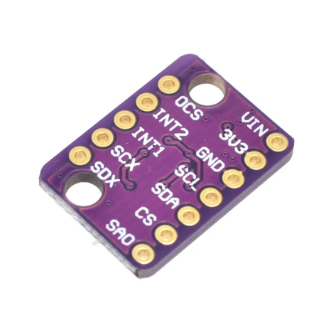
BMI160 sensor (taken from here).
-
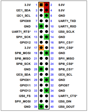
Expansion Header Connections of a Jetson Nano (taken from here).
-
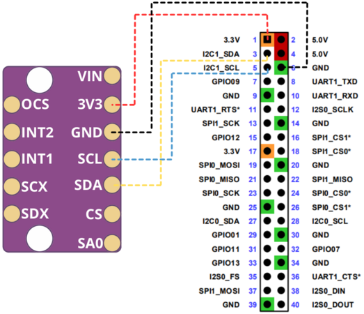
Connection of a BMI160 sensor.


