SDIO signal debugging
Software Integration Overview =
I was integrating the Atheros AR6003 SDIO WiFi driver when I ran into a problem where after many SDIO transfer occurred correctly, one transfer didn't complete. I reran a handful of times and it always got stuck at the same place. I enabled some kernel debug output and saw the following:
Kernel SDIO data transfer debug output
mmc0: starting CMD53 arg 14080018 flags 000001b5
mmc0:     blksz 24 blocks 1 flags 00000200 tsac 1000 ms nsac 0
davinci_mmc davinci_mmc.0: block read, 1 blocks of 24 bytes
davinci_mmc davinci_mmc.0:   DTO 0 cycles + 1000000000 ns
davinci_mmc davinci_mmc.0: CMD53, arg 0x14080018, R1/R5/R6/R7 response
mmc0: req done (CMD53): 0: 00001000 00000000 00000000 00000000
mmc0:     24 bytes transferred: 0
davinci_mmc davinci_mmc.0: Spurious interrupt 0x0000
mmc0: starting CMD53 arg 10100080 flags 000001b5
mmc0:     blksz 128 blocks 1 flags 00000200 tsac 1000 ms nsac 0
davinci_mmc davinci_mmc.0: block read, 1 blocks of 128 bytes
davinci_mmc davinci_mmc.0:   DTO 0 cycles + 1000000000 ns
davinci_mmc davinci_mmc.0: CMD53, arg 0x10100080, R1/R5/R6/R7 response
mmc0: req done (CMD53): 0: 00001000 00000000 00000000 00000000
mmc0:     128 bytes transferred: 0
mmc0: starting CMD53 arg 941f0080 flags 000001b5
mmc0:     blksz 128 blocks 1 flags 00000100 tsac 1000 ms nsac 0
davinci_mmc davinci_mmc.0: block write, 1 blocks of 128 bytes
davinci_mmc davinci_mmc.0:   DTO 0 cycles + 1000000000 ns
davinci_mmc davinci_mmc.0: CMD53, arg 0x941f0080, R1/R5/R6/R7 response
mmc0: req done (CMD53): 0: 00001000 00000000 00000000 00000000
mmc0:     128 bytes transferred: 0
mmc0: starting CMD53 arg 9408fa03 flags 000001b5
mmc0:     blksz 3 blocks 1 flags 00000100 tsac 1000 ms nsac 0
davinci_mmc davinci_mmc.0: block write, 1 blocks of 3 bytes
davinci_mmc davinci_mmc.0:   DTO 0 cycles + 1000000000 ns
davinci_mmc davinci_mmc.0: CMD53, arg 0x9408fa03, R1/R5/R6/R7 response
For those not too familiar with SDIO, CMD53 is the multi-byte read/write command.
Kernel wait_for_completion timeout message
After seeing the start of the 3 byte CMD53 write (transfer data to SDIO card), any more data output until 120 seconds passed and then I saw:
INFO: task kmmcd:194 blocked for more than 120 seconds.
"echo 0 > /proc/sys/kernel/hung_task_timeout_secs" disables this message.
kmmcd         D c02ed2e8     0   194      2 0x00000000
Backtrace:
[<c02ecff8>] (schedule+0x0/0x380) from [<c02ed9a0>] (schedule_timeout+0x20/0x1f4)
[<c02ed980>] (schedule_timeout+0x0/0x1f4) from [<c02ed7fc>] (wait_for_common+0xf4/0x1bc)
 r7:7fffffff r6:c551de4c r5:c54d92c0 r4:c551ddf8
[<c02ed708>] (wait_for_common+0x0/0x1bc) from [<c02ed954>] (wait_for_completion+0x18/0x1c)
[<c02ed93c>] (wait_for_completion+0x0/0x1c) from [<c02340e0>] (mmc_wait_for_req+0x1e0/0x200)
[<c0233f00>] (mmc_wait_for_req+0x0/0x200) from [<c0237bd8>] (mmc_io_rw_extended+0x17c/0x1e4)
 r7:00000001 r6:00000003 r5:c551de7c r4:c551ded4
[<c0237a5c>] (mmc_io_rw_extended+0x0/0x1e4) from [<c0238cf4>] (sdio_io_rw_ext_helper+0x154/0x18c)
[<c0238ba0>] (sdio_io_rw_ext_helper+0x0/0x18c) from [<c0238dac>] (sdio_memcpy_toio+0x28/0x30)
[<c0238d84>] (sdio_memcpy_toio+0x0/0x30) from [<bf001c00>] (async_task+0x444/0x78c [ar6000])
[<bf0017bc>] (async_task+0x0/0x78c [ar6000]) from [<c0057770>] (kthread+0x88/0x90)
[<c00576e8>] (kthread+0x0/0x90) from [<c0044cfc>] (do_exit+0x0/0x640)
 r7:00000000 r6:00000000 r5:00000000 r4:00000000
The last driver function before it goes into kernel APIs is mmc_wait_for_req(). This is waiting for the MMC/SD sub-system to finish the data transfer. From the SDIO spec, the only reason the transfer didn't complete is XXXX.
I wanted to get some technical support, but before asking I needed to find out if the ARM wasn't sending the data or if the SDIO card was pacing off the data transfer from the ARM.
SDIO hardware Overview

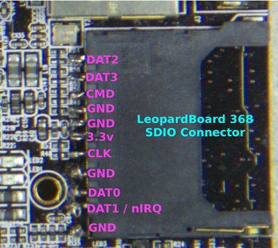
The SD / SDIO card pinout is:
| SDIO Pin |
Signal |
|---|---|
| 9 | DAT2 |
| 1 | DAT3 |
| 2 | CMD |
| 3 | GND |
| 4 | 3.3V |
| 5 | CLK |
| 6 | GND |
| 7 | DAT0 |
| 8 | DAT1 / nIRQ |
Adding probe clip attachment points

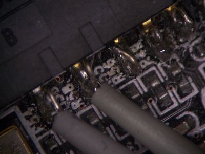
To allow the logic state analyzer clips to grab onto the pins, I used small needle-nose pliers and wirewrap wire. I made a small loop of wire, overlapping the wire by 1/4 turn, using the very tip of the needle-nose pliers for the form. Then I soldered the loop, with the overlap on the bottom, to the SD connector's metal tabs. Once the wire loop was soldered in place, I used an exacto knife to support the solder joint and wiggled the wire until it broke right at the loop. This provided a simple way to clip each probe onto a signal and also allowed the modification to be left in place without effecting the board usability.
