
Spherical Video PTZ/Getting Started/Projections Used: Difference between revisions
(Created page with "<noinclude> {{Spherical Video PTZ/Head|previous=|next=|metakeywords=}} </noinclude> =Overview= This section provides the theoretical explanations of the Equirectangular and Rectilinear projections, which are used on the Spherical Video PTZ. =Equirectangular Projection= Equirectangular images, also referred to as 360° images, capture a panoramic view from a fixed point where the imaging system is positioned. These images encapsulate a complete 360° perspective, allow...") |
|||
| (6 intermediate revisions by 3 users not shown) | |||
| Line 1: | Line 1: | ||
<noinclude> | <noinclude> | ||
{{Spherical Video PTZ/Head|previous=|next=|metakeywords=}} | {{Spherical Video PTZ/Head|previous=Getting Started/Spherical Video PTZ|next=Getting Started/Evaluating the Product|metakeywords=}} | ||
</noinclude> | </noinclude> | ||
=Overview= | ==Overview== | ||
This section provides the theoretical explanations of the Equirectangular and Rectilinear projections, which are used on the Spherical Video PTZ. | This section provides the theoretical explanations of the Equirectangular and Rectilinear projections, which are used on the Spherical Video PTZ. | ||
==Equirectangular Projection== | |||
=Equirectangular Projection= | Equirectangular images, also referred to as 360° images, capture a panoramic view from a fixed point where the imaging system is positioned. These images encapsulate a complete 360° perspective, allowing all surrounding information to be displayed within a single flat image. To illustrate this concept, consider visualising the Earth as a sphere and then "unfolding" it along the central meridian (shown by the red lines in the accompanying image). This "unfolding" process transforms the spherical surface into a plane image. Please note, that the resulting plane maintains a unique aspect ratio of 2:1, because of the vertical range covers 180° and the horizontal range covers 360° after the unfolding procedure. | ||
Equirectangular images, also referred to as 360° images, capture a panoramic view from a fixed point where the imaging system is positioned. These images encapsulate a complete 360° perspective, allowing all surrounding information to be displayed within a single flat image. To illustrate this concept, consider | |||
<gallery widths="300px" heights="200px" mode="packed-hover"> | <gallery widths="300px" heights="200px" mode="packed-hover"> | ||
File:Meridians.png|Meridians on earth globe. | File:Meridians.png|Meridians on earth globe.|Alt=Example of Equirectangular Projection | ||
File:Map with meridians.png|Meridians on earth map. | File:Map with meridians.png|Meridians on earth map.|Alt=Example of Equirectangular Projection | ||
</gallery> | </gallery> | ||
=Rectilinear Projection= | ==Rectilinear Projection== | ||
The Rectilinear projection, also referred to as the Gnomonic Projection, is a method used to project the surface of a sphere (or a 360° image) onto a plane. Typically, the plane onto which the surface points are mapped is tangent to the sphere at a single point. This projection is accomplished by using the | The Rectilinear projection, also referred to as the Gnomonic Projection, is a method used to project the surface of a sphere (or a 360° image) onto a plane. Typically, the plane onto which the surface points are mapped is tangent to the sphere at a single point. This projection is accomplished by using the centre of the sphere as the projection point. It's important to note that the resulting plane does not intersect the centre of the sphere. The diagram below provides a visual example of this process: | ||
<br> | <br> | ||
[[File:Rectilinear-projection.png|thumbnail|center|640px|Rectilinear projection: great circle projection example]] | [[File:Rectilinear-projection.png|thumbnail|center|640px|Rectilinear projection: great circle projection example|alt=Example of Rectilinear Projection]] | ||
| Line 28: | Line 26: | ||
<br> | <br> | ||
==Equirectangular to Rectilinear Projection== | |||
Now that both projections' workings are clear, let's delve into the crucial details: why is this transformation necessary? | |||
If we round up an Equirectangular image, we can construct a spherical image where the data is accurately positioned on the surface of the sphere. However, if a user chooses to crop the Equirectangular image directly, it would lead to an issue: the resulting image would exhibit irregularities due to the curvature of the sphere. Therefore, projecting this image into a Rectilinear image resolves the problem of perturbations in the desired output. | |||
<noinclude> | <noinclude> | ||
{{Spherical Video PTZ/Foot||}} | {{Spherical Video PTZ/Foot|Getting Started/Spherical Video PTZ|Getting Started/Evaluating the Product}} | ||
</noinclude> | </noinclude> | ||
Latest revision as of 15:11, 2 October 2024
| Spherical Video PTZ |
|---|
| Getting Started |
| User Guide |
| Examples |
| Performance |
| Contact Us |
Overview
This section provides the theoretical explanations of the Equirectangular and Rectilinear projections, which are used on the Spherical Video PTZ.
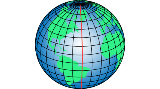
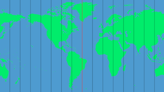
Equirectangular Projection
Equirectangular images, also referred to as 360° images, capture a panoramic view from a fixed point where the imaging system is positioned. These images encapsulate a complete 360° perspective, allowing all surrounding information to be displayed within a single flat image. To illustrate this concept, consider visualising the Earth as a sphere and then "unfolding" it along the central meridian (shown by the red lines in the accompanying image). This "unfolding" process transforms the spherical surface into a plane image. Please note, that the resulting plane maintains a unique aspect ratio of 2:1, because of the vertical range covers 180° and the horizontal range covers 360° after the unfolding procedure.
-
Alt=Example of Equirectangular Projection
-
Alt=Example of Equirectangular Projection


Rectilinear Projection
The Rectilinear projection, also referred to as the Gnomonic Projection, is a method used to project the surface of a sphere (or a 360° image) onto a plane. Typically, the plane onto which the surface points are mapped is tangent to the sphere at a single point. This projection is accomplished by using the centre of the sphere as the projection point. It's important to note that the resulting plane does not intersect the centre of the sphere. The diagram below provides a visual example of this process:

The term "rectilinear" in the Rectilinear projection refers to its use of straight lines for the projection. This means that lines that are parallel in the real world remain parallel in the projection. Additionally, it is worth noting that every great circle (which is the largest circle that can be drawn on any given sphere) is transformed into a straight line in the resulting plane during this projection process.
Equirectangular to Rectilinear Projection
Now that both projections' workings are clear, let's delve into the crucial details: why is this transformation necessary?
If we round up an Equirectangular image, we can construct a spherical image where the data is accurately positioned on the surface of the sphere. However, if a user chooses to crop the Equirectangular image directly, it would lead to an issue: the resulting image would exhibit irregularities due to the curvature of the sphere. Therefore, projecting this image into a Rectilinear image resolves the problem of perturbations in the desired output.